Author: Zhang Dongchang
In 2024, Chengdu Miji Technology Co., Ltd. successfully delivered an advanced infrared near-field optical microscopy system to a university in Shenzhen. The optical path schematic of the system is shown in Figure 1, consisting of a laser guidance system, a beam expansion system and a pseudo-heterodyne system. The main body of the system is composed of a domestically produced 6.5 µm quantum cascade laser (QCL) and a dedicated near-field atomic force microscope (AFM) main unit. By integrating these devices, the system achieves high-resolution infrared near-field imaging, providing outstanding performance and precise measurement capability — a powerful tool for researchers to explore and analyze material characteristics in the microscopic domain.
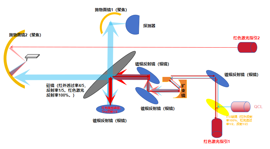
Figure 1: Schematic of the infrared near-field optical path
System Functions:
The system mainly implements infrared near-field imaging. Because infrared light is invisible, this infrared near-field optical system adopts a red-light/infrared overlapping guidance strategy. Taking advantage of ITO (indium tin oxide) glass's property of totally reflecting infrared light while semi-transmitting visible light, the red laser guidance beam 1 in Figure 1 is made to completely overlap with the infrared laser from the 6.5 µm QCL (quantum cascade laser) through an ITO mirror, thereby achieving "visualized" focusing of the infrared light onto the tip. The overlapped beam passes through a mirror and a reflective beam expander (10× expansion) before entering the pseudo-heterodyne system. The system includes a silicon plate with an infrared transmission-to-reflection ratio of 8:2, which properly distributes the infrared light between near-field imaging and the pseudo-heterodyne reference. Finally, through the integrated atomic force microscope system, the near-field imaging function of an infrared scanning near-field optical microscope (SNOM) is successfully realized. This system design offers extremely high imaging precision and resolution, providing an advanced tool for scientific research.
Light source: A domestically produced 6.5 µm quantum cascade laser (QCL) provides a stable infrared source, meeting high-precision imaging requirements.
Optical path design: Considering that the QCL output is a point source and invisible, the optical path design includes a beam expansion system and a laser guidance system to accurately focus the infrared light onto the probe. The beam expansion system uses a reflective beam expander (10× expansion) to expand the laser beam for better beam quality, facilitating a smaller focused spot.
Pseudo-heterodyne detection: The pseudo-heterodyne system contains a silicon plate with an infrared transmission-to-reflection ratio of 8:2. With a precise optical path, the reference beam and the signal beam interfere here, enhancing the signal intensity and thereby improving imaging resolution.
Atomic force microscope (AFM): The system integrates a dedicated near-field AFM, which achieves nanoscale imaging and measurement through the interaction between the probe and the sample surface. After the infrared signal is focused into a region of a few hundred nanometers, the AFM probe can precisely position and scan the sample surface.
Data acquisition and analysis: The system is equipped with advanced data acquisition and analysis software, capable of processing and analyzing the acquired near-field imaging data in real time, providing high-resolution infrared spatial information.
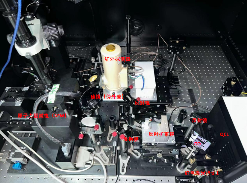
Figure 2: Infrared near-field optical microscopy system
Near-Field Measurement Signal Analysis
The infrared near-field optical microscopy system (IR-SNOM) is a mature and highly precise technology that can surpass the diffraction limit of conventional optical microscopes to achieve nanoscale high-resolution imaging. Therefore, the purity of the extracted near-field signal is especially important. In this system, the lock-in amplifier can demodulate near-field signals up to the fifth order (the higher the order, the stronger and purer the near-field signal). Figure 3 shows the lock-in demodulated fifth-order signal; the red laser at the probe tip on the right is the guidance laser. It can be seen intuitively that the infrared light is focused onto the tip to extract a purer near-field signal.
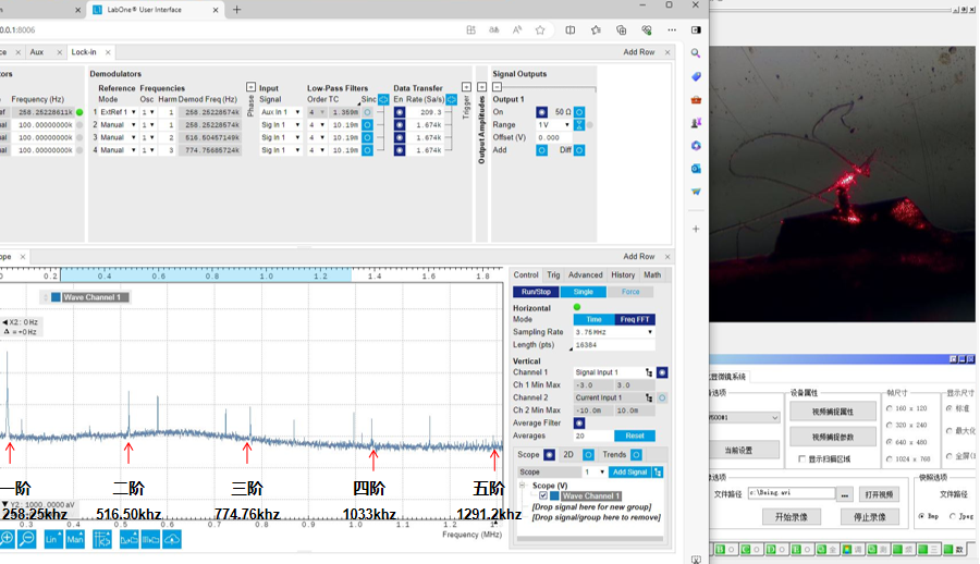
Figure 3: Fifth-order signal
Near-Field Imaging
In this test, we selected the following three samples to characterize the infrared near-field optical microscopy system: (a) a grating structure, (b) boron nitride nanotubes, and (c) cubic boron nitride.
In the test of (a) the grating structure, the spacing between gratings is about 60 nm. In first- and second-order imaging, the system demonstrated excellent near-field resolution, accurately performing infrared near-field imaging of the grating surface. This shows that the system has outstanding performance when handling high-resolution structures.
In the tests of (b) boron nitride nanotubes and (c) cubic boron nitride, the boron nitride and substrate signals formed a clear contrast. In the infrared near-field imaging of (c) cubic boron nitride, significant bright lines appeared at the sample edges, indicating that the near-field signal is very strong. This phenomenon further verifies the system's high sensitivity and high resolution in detecting sample edges and fine features.
Through testing these three samples, our infrared near-field optical microscopy system demonstrated excellent performance and reliability across different types of samples, providing high-resolution, high-contrast infrared near-field imaging results and offering strong support for further materials and structure research.
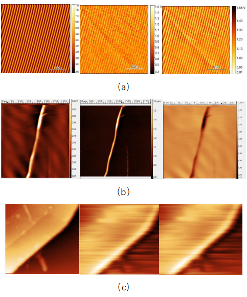
Figure 4: (a) grating structure, (b) boron nitride nanotubes, (c) cubic boron nitride.
From left to right: topography imaging, first-order signal imaging, third-order signal imaging